8: The Pin Wheel Escapement
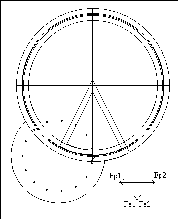
Drawing the pin wheel escapement proved to be a considerable challenge. A
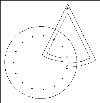
simulation of the action of the pin wheel escapement is interesting when compared with that of the Graham escapement: the action is different because of the directions of the forces Fe and Fp, but the results are the same.
You will have noticed that, in the Graham escapement, the angle Fe1Fe2 was
90º, and so was the angle Fp1Fp2. In the pin wheel escapement, the angle Fe1Fe2 is zero (both go in the same direction), and the angle Fp1Fp2 is 180º. However, the angle Fe1Fp1 is 90º, and so is the angle Fe2Fp2. Another consideration in this drawing is that the thickness of each pallet is equal to half the arc between two escape wheel teeth, as in the Graham escapement, minus enough pallet thickness to allow for drop. The angle of the pallet's impulse face needs to be 45º relative to Fe. The pallet locking face should be designed about circles, as in the Graham, in order to preserve the dead-beat nature of the action.
 |
Changing the pallet circle's diameter does not affect the number of teeth between the pallets, as it does in the Graham. However, it does affect the angle of swing of the pallets (from side to side). If the pallet circle radius were increased, the angle of swing could be decreased, which is desirable for a fine regulator. This would make it possible to minimize the circular error in the movement of the pendulum.
The lack of popularity of the pin wheel escapement could be explained in the
difficulty in manufacturing the pallets because of their intolerance for error: if the design were not perfect, it probably would not work at all, which becomes very
obvious when preparing drawings for a simulation. The recoil escapement, on the other hand, could be imprecisely designed, and it would be much more likely to work.
 |
Go to Chapter 9
Table of Contents
Escapements in Motion
Clock Repair Main Page
Links Page