11: Efficiency in Numbers (II)
The most difficult part of an escapement
drawing is the calculations for the verge circle radii, which is critical for the Pin Wheel
escapement. Here there are seven circles (not drawn to scale).
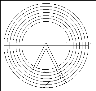 |
If the 4th circle, between
the pallets, has a radius of 6", the others must be calculated from this circle. If the escape
wheel's pin has a diameter of 1/16 of an inch, or 0.0625", the gap between the two pallets
must be greater than this, say 0.1": the radii of the 3rd and the 5th circles would be 5.95"
and 6.05" respectively. The gap between the locking face of the entry pallet and the
let-off corner of the exit pallet must be equal to the arc between two escape wheel pins
(less the diameter of one pin and less the allowance for drop). If the escape wheel had
fifteen pins and a radius of 3", its arc would be:
arc = 3 x (24º x pi) / 180 = 1.26"
(because 24º x 15 = 360º), but you allow 1.5º for drop:
arc = 3 x (22.5 x pi) / 180 = 1.18"
and for the pin diameter: arc = 1.18 - 0.0625 = 1.12" (to two decimal places).
The radius of the 1st circle is therefore: 6 - (1.12 / 2) = 5.44"
The radius of the 7th circle is 6.56". The radius of the 2nd circle is half way between the 1st and the 3rd:(5.95 + 5.44) / 2 = 5.70"
The radius of the 6th circle is half way between the 5th and the 7th:(6.05 + 6.56) / 2 = 6.30"
The radius of the 4th circle may appear to be arbitrary because it is not determined
by the tooth span between the pallets, as it would be for the Graham, Recoil, and Brocot.
It is determined only by the desired angle of pendulum swing.
Consider a pallet circle that was determined by a tooth span, such as the Graham
escapement with the 15 tooth escape wheel in chapter 10. It had a tooth span of 5.5 teeth,
so the angle between the pallets was: (5.5 / 15) x 360 = 132º, half of which was 66º. The
escape circle radius was 3", so the pallet circle radius could be found by
triangulation:
 |
tan (66) = Rp / Re
Rp = Re x tan (66) = 3 tan (66) = 6.74"
Continuing with the Graham in chapter 10, its escape wheel had a radius of 3", so
the arc between two teeth was:
arc = (3" x 24º x pi) / 180º = 1.26"
The arc per beat (12º): 1.26 / 2 = 0.63"
Allow 1.5º for drop:
arc = (0.63 x 10.5º) / 12º = 0.55"
This is the thickness of the pallets.
Therefore, the entry pallet locking face has a pallet circle radius of:
6.74 + 0.27 = 7.01"
and the exit pallet locking face has a pallet circle radius of:
6.74 - 0.27 = 6.47".
Replacing the Pallets.
Suppose a British grandfather clock movement were brought for repair with no
pallets. You determine by inspecting the 30 tooth escape wheel that the clock had a
recoil escapement. The distance between the escape wheel bushing and the pallet
bushing is 1.6". The escape wheel has a diameter of 2", so the escape circle's radius is
1". First, draw the pallet you want over an ideal Graham pallet and remove the
latter.
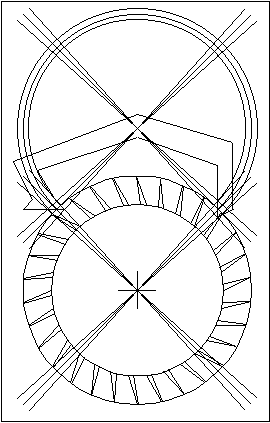 |
Draw two triangles using this
arrangement:
cos (A) = 1 / 1.6
A = acos (1 / 1.6) = 51.3º
Use this to determine the tooth span:
30 x (2 x 51.3 / 360) = 8.553
so you should use a span of 8.5 teeth.
 |
To recalculate the angle A: (8.5 x 360) / (2
x 30) = A = 51º
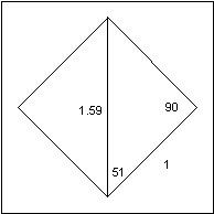 |
Assume a small error in measurement:
cos (51) = 1 / h
h = 1 / cos (51) = 1.59"
The pallet angle is : 180 - 90 - 51 = 39º
The pallet circle radius is:
Rp = 1 x tan (51) = 1.23
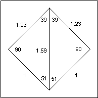 |
By comparing this drawing with the one on
the previous page, calculate the positions of the tips of the pallets. The inside tip of the
entry pallet needs to be at a slightly smaller angle from vertical:
Angle = 39 - (3 x (1 / 1.23) = 36.6º
and the radius:
r = 1.23 - ((2 x pi) / (4 x 30)) = 1.18"
Similarly for the exit pallet:
Angle = 36.6º.
r = 1.23 + ((2 x pi) / (4 x 30)) = 1.28"
The rest of the pallet could be drawn any way you wish.
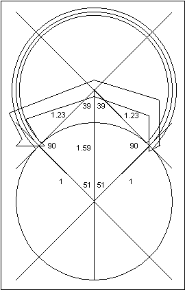 |
To explain the numbers
above, the escape wheel has an angle of 12º between two teeth. A tooth will travel 6º per
beat. The pallet angle lines were divided into 3º on either side. Since the pallet radius is
1.23 and the escape radius is 1", multiply the escape angle of 3º by the ratio of the radii.
Since the pallet radius is larger, the pallet arc is smaller than the escape wheel arc (which
has an angle of 3º).
For the radius calculation, decrease the
pallet radius on the entry pallet by the amount of a quarter of the arc between two escape
wheel teeth, and increase the pallet radius on the exit pallet similarly. This is only a close
approximation because the change in the pallet circle's radius is assumed to be equal to
the arc of the escape circle, but an arc is not a straight line.
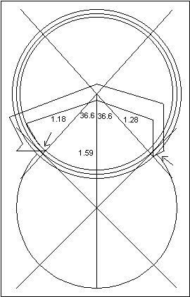 |
Once the pallet blank is made, it must be fitted because there is no drop. By filing on
the surfaces pointed to by the arrows, some inside and outside drop could be created.
When designing a Graham pallet, the issue becomes more complicated because of lock. I
would suggest that the best way to design the pallets would be to make the blank with
impulse faces that have angles relative to Fe smaller than 45º, such as 25º. When fitting
the pallets to the clock, file first on the inside and outside surfaces to create enough
inside and outside drop. Then file on the impulse face to increase the impulse angle until
the lock has been reduced to about 1º. To be practical in a manufacturing situation, the
measurement deviations must be accounted for to keep rejects statistically below 5%.
The need to account for these deviations means that a compromise situation arises
because fitting each verge by hand would interfere with mass production and economies
of scale.
Fitting a Brocot pallet requires the calculation of the pallet circle's radius. If the
escape wheel rotates 6º per beat, and its radius were 1", the arc would be:
arc = (1 x 6 x pi) / 180 = 0.105"
I suggest 1.5º of drop, so the radius of the pallet's circle should be:
r = (1 x 4.5 x pi) / 180 = 0.08"
Using the recoil example, the Brocot pallet should be positioned such that the point
where the pallet releases the escape tooth should have a pallet circle radius of 1.18" and
an angle of 36.6º from vertical for the entry pallet, and a radius of 1.28" and an angle of
36.6º for the exit pallet. Then the lock and drop could be further adjusted by raising or
lowering the pallets, or by changing the gap between the pallets.
By studying the above example, you could see how you could use one type of
escapement for the calculations, and then apply them to the type of escapement you want
to create. A step-by-step process makes the calculations easier.
Escapements in Motion
Clock Repair Main Page
Links Page