15: Improving the Design
In order to maximize efficiency, the impulse face of each pallet should have an angle half way between its corresponding escape circle radius line and pallet circle radius line. Looking at the design with equidistant impulse, if the angle between lines (2) and (4) were 90º, then the impulse face's angle should be 45º and line (15) is half way between lines (2) and (4). A change in design is needed in practice because the escape wheel's teeth are too narrow and therefore too fragile. Thus far, I have assumed that the escape tooth's impulse face should be parallel to the pallet's impulse face in the drawing. However, the simulation reveals, as suspected, that the lines do not remain parallel during impulse:
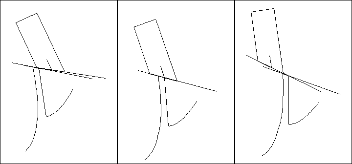 |
This means that they need not be parallel in the design. If the pallet's impulse face
remained unchanged, the efficiency of the escapement would remain unchanged, and we
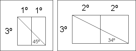
could change the shape of the escape tooth without sacrificing efficiency. The span of the
tooth's impulse face could be increased from 2º to 4º so as to draw a wider tooth. The
amount of lock would remain unchanged at 3º for the purpose of the drawing:
 |
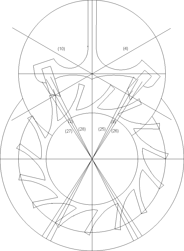
If the escape tooth occupied a span of 4º and there were 2º of drop, the pallet would
occupy a span of 6º, for a total span of 12º per beat. New pallets must be drawn.
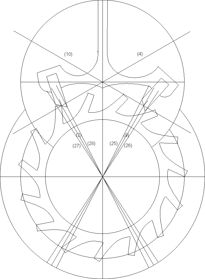
Rotate line (9) counterclockwise by 3º to get line (25), and clockwise by 3º
to get line (26). Rotate line (2) counterclockwise by 3º to get line (27), and clockwise by
3º to get line (28). Rotate line (27) clockwise by 15º and draw the locking face. Draw the
rest of the pallet as before, then duplicate it and rotate it clockwise by 60º, placing it on
the exit side. The pallets are narrower, but the teeth are wider. Notice the difference in
the angles of the pallet and escape tooth impulse faces.
 |
Another way to make a stronger tooth would be to trace the path of the pallet during
the simulation, and then to draw the curve on the back side of the tooth again.
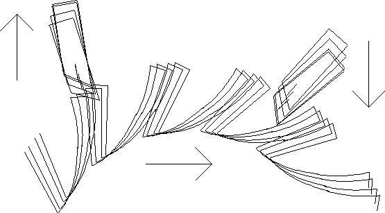 |
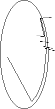
If the simulation were superimposed for the action of the escapement as the tooth pushed on
the entry pallet, the exit pallet enters the space between two teeth.
The distance between the exit pallet and the tooth that just passed it could be measured by drawing lines from the pallet to the
tooth. These lines could be used as a guide when drawing a new curve. Move the ellipse
to other positions and change its shape until you trace a path for a new curve more like the path of the pallet. If you draw the lines on the tooth next to the
exit pallet and are drawing the new tooth next to the entry pallet, you must rotate the
lines by 24º for every tooth in between, that is, by 72º counterclockwise. I drew a new
escape wheel using the same principles as in the first drawing plus these lines as a guide.
Unfortunately, the path of the pallet would be very difficult to predict before doing a
simulation.
 |
It is preferable to draw the first escape wheel with narrow teeth because it would be
much more likely to work in a simulation. For the same reason, I recommend designing
the first drawing with no less than 2º of lock and 2º of drop. The simulation would show
the lock and drop more clearly and it would be more forgiving if errors were made. In
addition, the simulation would be much more likely to work when changes in design are
made, such as when going from equidistant impulse to equidistant lock. Once you have
some practice, then try a design with the theoretically correct 1º of lock and 1º of drop.
You would find that any error made in the drawing would result in binding or recoil.
This drawing has the same, smaller pallets and a new escape wheel:
 |
This drawing does not include the pallet fork and the roller table, primarily because
of the math involved. These are added in Chapter 22.
Go to Table of Contents
Go to Escapements