20: The Chronometer Escapement
The most important advantage that the Chronometer Escapement has over the Swiss
Lever is that lubrication of the escape wheel teeth is not required: the balance's impulse
pallet and the escape tooth appear to roll together rather than to slide across one another
(as in the Swiss Lever), so there is much less friction in the Chronometer escapement.
Since the lubricant may change viscosity as the temperature changes, and may even dry
up over time, it is preferable not to lubricate the escapement unless necessary: since the
Chronometer escapement has a much lower friction loss, the ability to make it run dry
would result in a more consistent timekeeper.
While the principles of this escapement are straightforward, the drawing is difficult
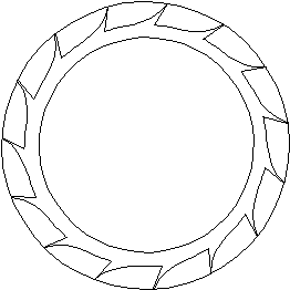
to create, and there is plenty of math involved. Draw a 15 tooth escape wheel inside a 6
inch diameter circle.
 |
Draw a 3.25 inch line from the center of the escape wheel to the edge of the circle.
Then draw a vertical line, which will represent the detent, a quarter of an inch away from
the edge of the circle. Rotate this line clockwise by 45º, and place it over the center of
the circle and crossing the detent line to create a triangle. The top right corner will become the balance's circle center. To calculate the
distance (T) between the two circle centers:
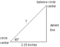 |
let T = 3.25 / cos 45 = 4.596"
You need to find the radius of the impulse pallet's circle (X), that is, the circle that
will trace the path of the impulse pallet. If the escape wheel rotates by 22º (24º less 2º for
drop) during impulse, you could draw the following triangles:
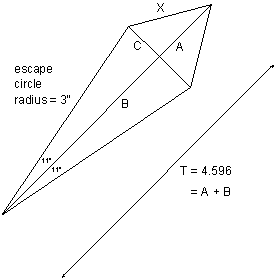 |
B = 3 cos 11 = 2.945 |
X = 1.747
Draw a circle with a radius of 1.747 inches and place its center on the point where the
detent line and the T line meet. Another method could be used to calculate X: it is shown
on page 73.
Once the impulse portion of the escapement it finished, it is necessary to calculate
the dimensions of the discharging pallet's circle and the gold spring's circle for the
detent. If the discharging pallet rotates by 30º, and the gold spring rotates by 2º, during
discharge, we get another set of triangles. (These are not drawn to scale.)
|
R cos 30 + G cos 2 = 6.5 |
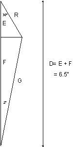 |
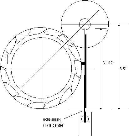
Draw a circle with a radius of 0.429" and place it such that its center lies on the
point where the detent line and line T intersect. The discharge pallet's circle will then be
centered inside the impulse pallet's circle. Draw the gold spring's line on the detent line
and make it 6.132 inches long from the point about which it would rotate, 6.5 inches
below the center of the impulse pallet's circle. The longer the gold spring's line, the
better, because the locking pallet would have a greater arc relative to the arc of the gold
spring's line as it rotates to discharge the escape wheel. I chose a length of 6.5 inches, or
twice the displacement from the horizontal line to the impulse pallet's circle
center.
Rotate the escape wheel until the impulse pallet's circle is centered between two
escape teeth. Then draw the detent pallet on the detent arm: place it just below the tooth,
as shown, and with a small amount of lock. The thick line next to the gold spring line
represents the detent arm. The rectangle below represents the base of the detent arm. The
gold spring's circle is not included in this drawing because of its size, but it would be
needed for the simulation.
 |
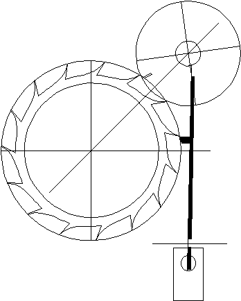
Rotate the detent arm and gold spring assembly clockwise by 1º, until the detent
pallet just releases the escape tooth. Rotate the discharge pallet counterclockwise by 8º.
Draw the impulse pallet at the edge of the impulse pallet's circle, just inside the escape
wheel's circle.
 |
Rotate the detent clockwise by 1º extra, and the discharge and impulse pallets
counterclockwise until the discharge pallet meets the gold spring. Then rotate the escape
wheel until it meets the impulse pallet. The discharge and impulse pallets must rotate by
enough to allow the escape wheel to move forwards until the tooth clears the detent
before the detent is released. Otherwise, there will be some bent escape teeth.
Go to Table of Contents
Go to Escapements